Modular Autonomous Rover
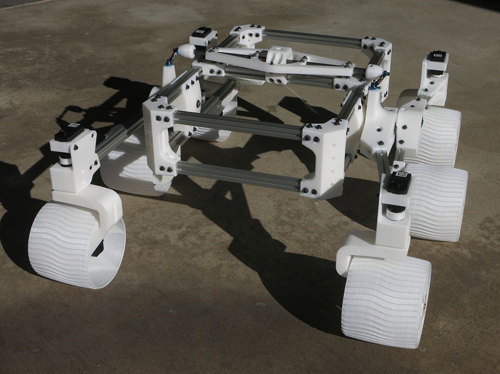
Open-source autonomous rover chassis built on the Sawppy Rover architecture, modified for locally available hardware in Bangladesh.
Manufacturing sponsorship secured
Manufacturing support is now in place from EasyEDA, JLCPCB, and JLC3DP. PCB and PCBA files have been submitted for fabrication, and the team is preparing for mechanical assembly.
About the project
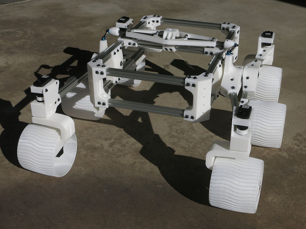
A rocker-bogie suspension rover chassis adapted from the Sawppy Rover project. The original uses LX-16A smart servos for both steering and drive. This build replaces them with DC gear motors and standard PWM servos that are locally available in Bangladesh at a fraction of the cost.
The chassis is designed to be the base for multiple rover applications. Swap the payload on top, keep everything underneath the same.
Build checklist
- ✓ Chassis design and hardware selection
- ✓ Motor mount and servo bracket redesign
- ~ 3D printing structural components
- ○ Custom PCBA for motor control and power
- ○ Chassis assembly and drivetrain test
- ○ Autonomous navigation (ROS 2)
- ○ Field testing
Based on Sawppy Rover
Derivative of the Sawppy Rover by Roger Random, published open-source. All credit for the original architecture goes to the Sawppy community.
What changed from Sawppy
| Component | Sawppy Original | This Build |
|---|---|---|
| Drive motor | LX-16A smart servo | JGB37-520 12V 100RPM DC gear motor |
| Steering | LX-16A smart servo | Hiwonder LDX-277 PWM servo |
| Motor control | Serial bus | Standard PWM / motor driver |
| Spline | Proprietary | 25T standard |
| Sourcing | Import only | Locally available in Bangladesh |
CAD and manufacturing files
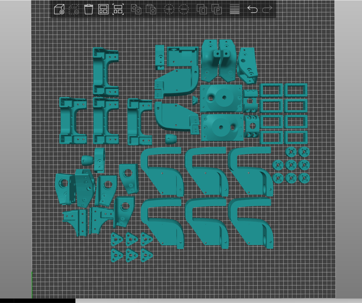
CAD is complete. Manufacturing files are prepared, and structural components have been submitted for JLC3DP manufacturing.
- ✓ Motor mounts for JGB37 form factor
- ✓ Servo brackets for LDX-277 dimensions
- ✓ Steering linkage alignment
- ✓ Coupler and hub interfaces
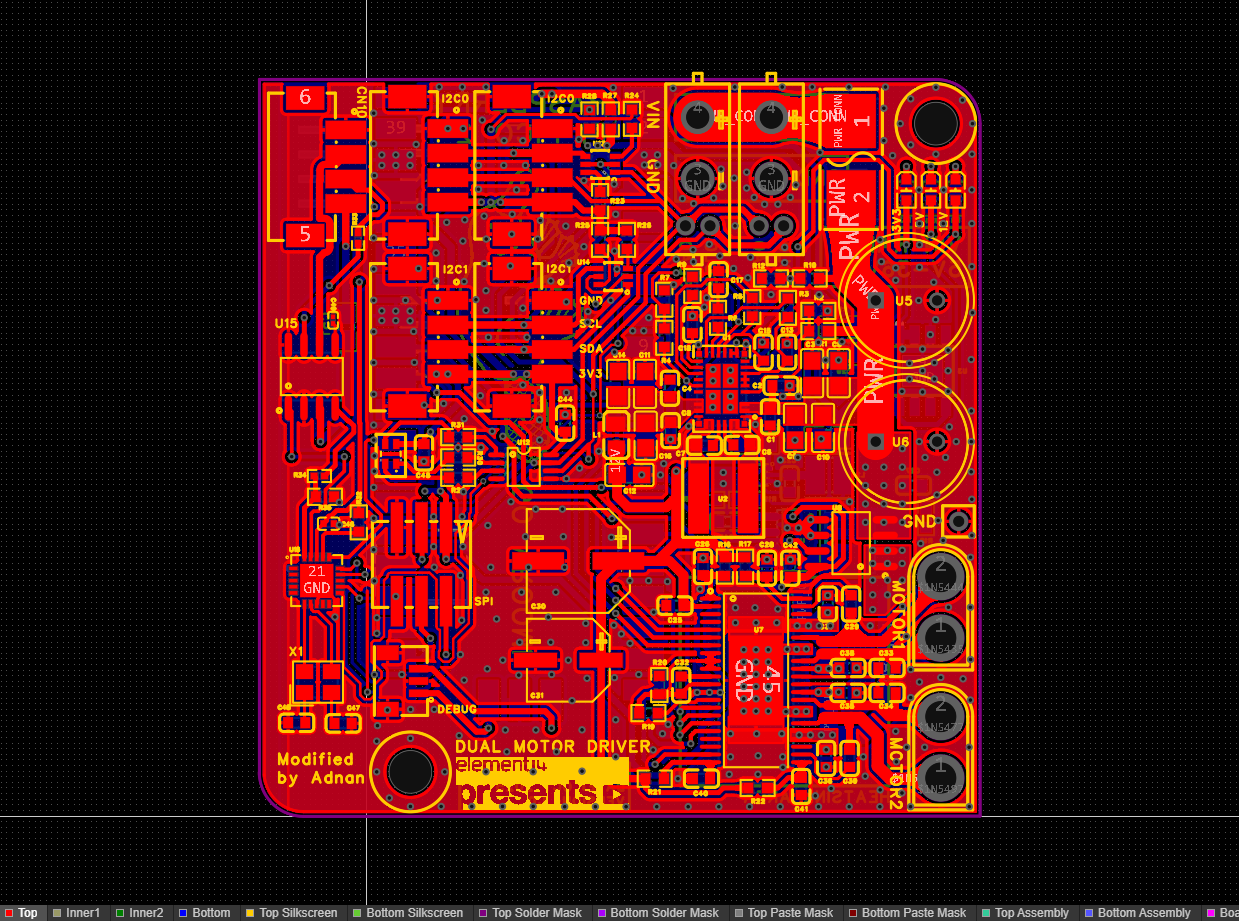
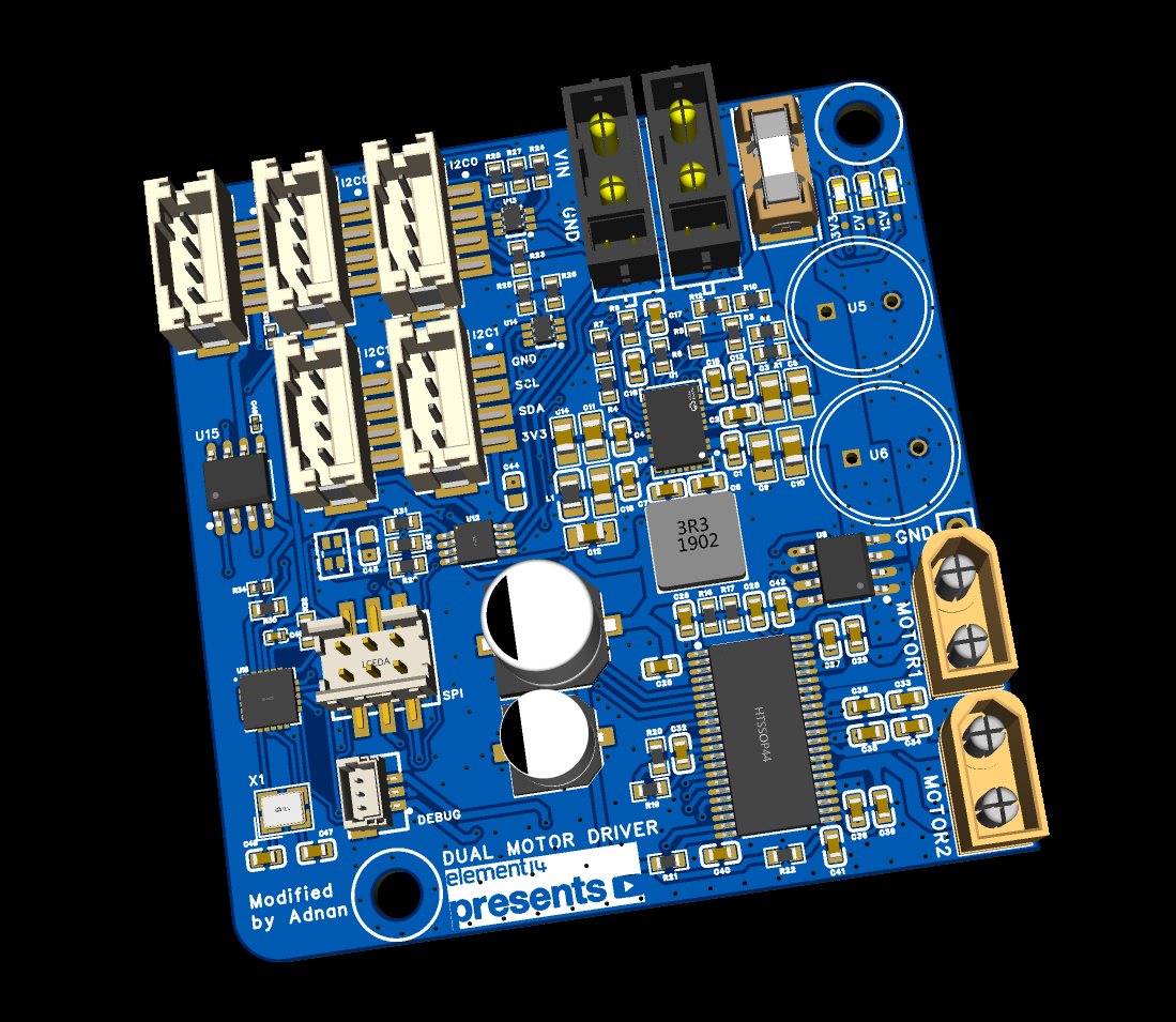
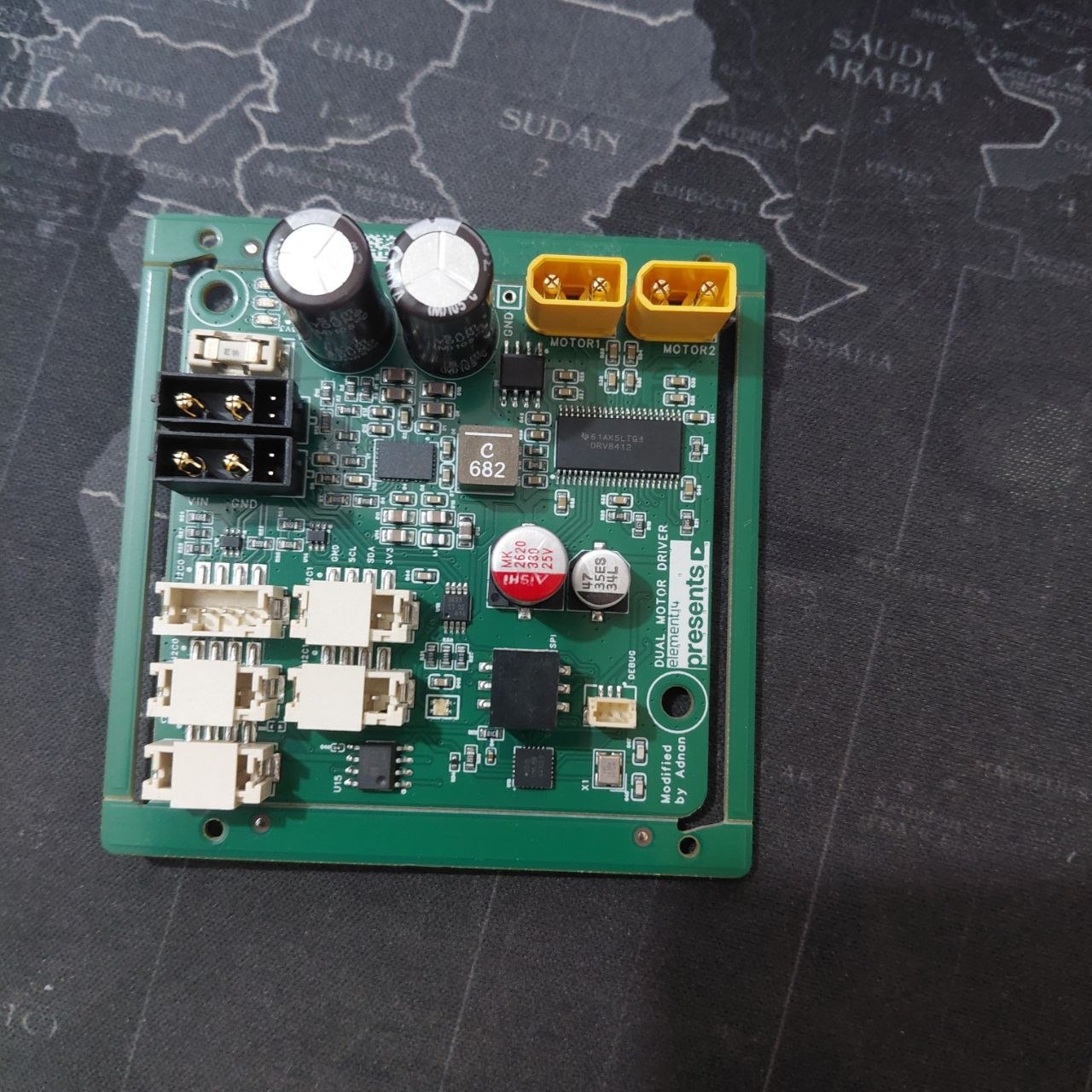
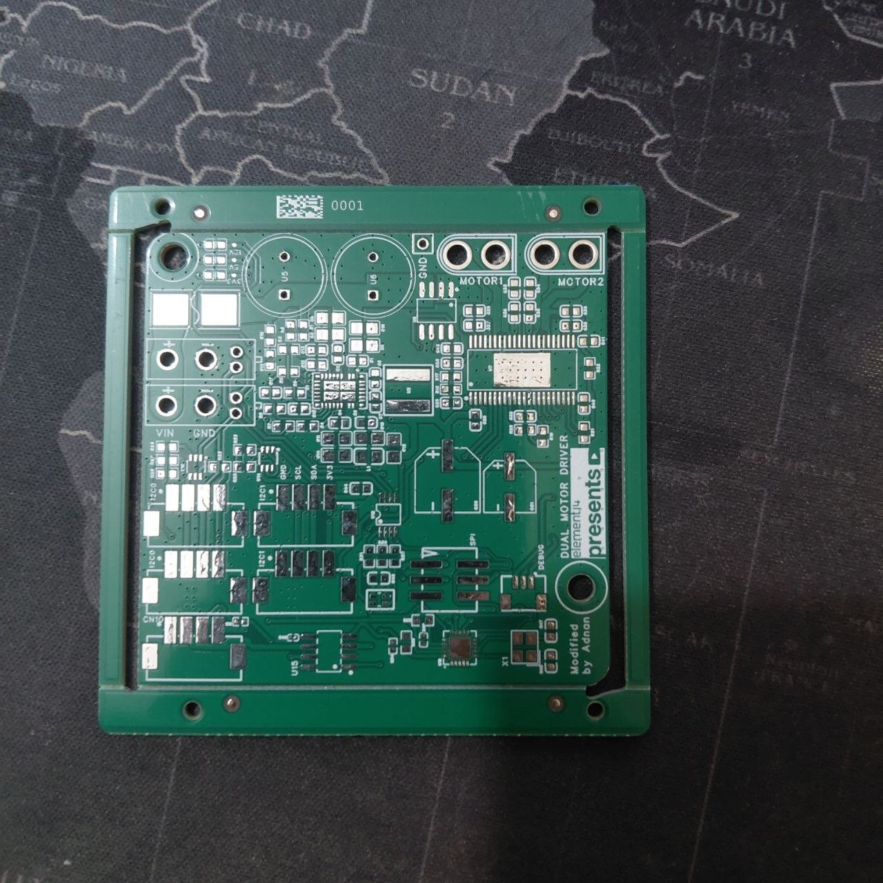
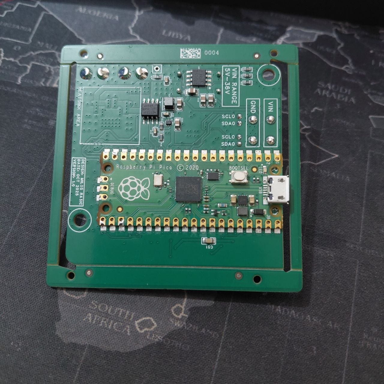
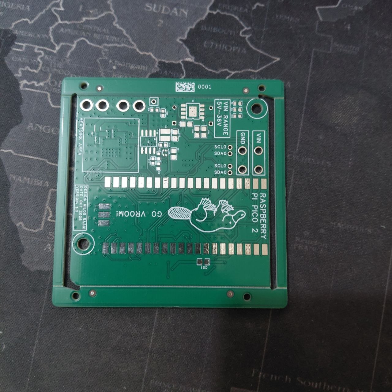
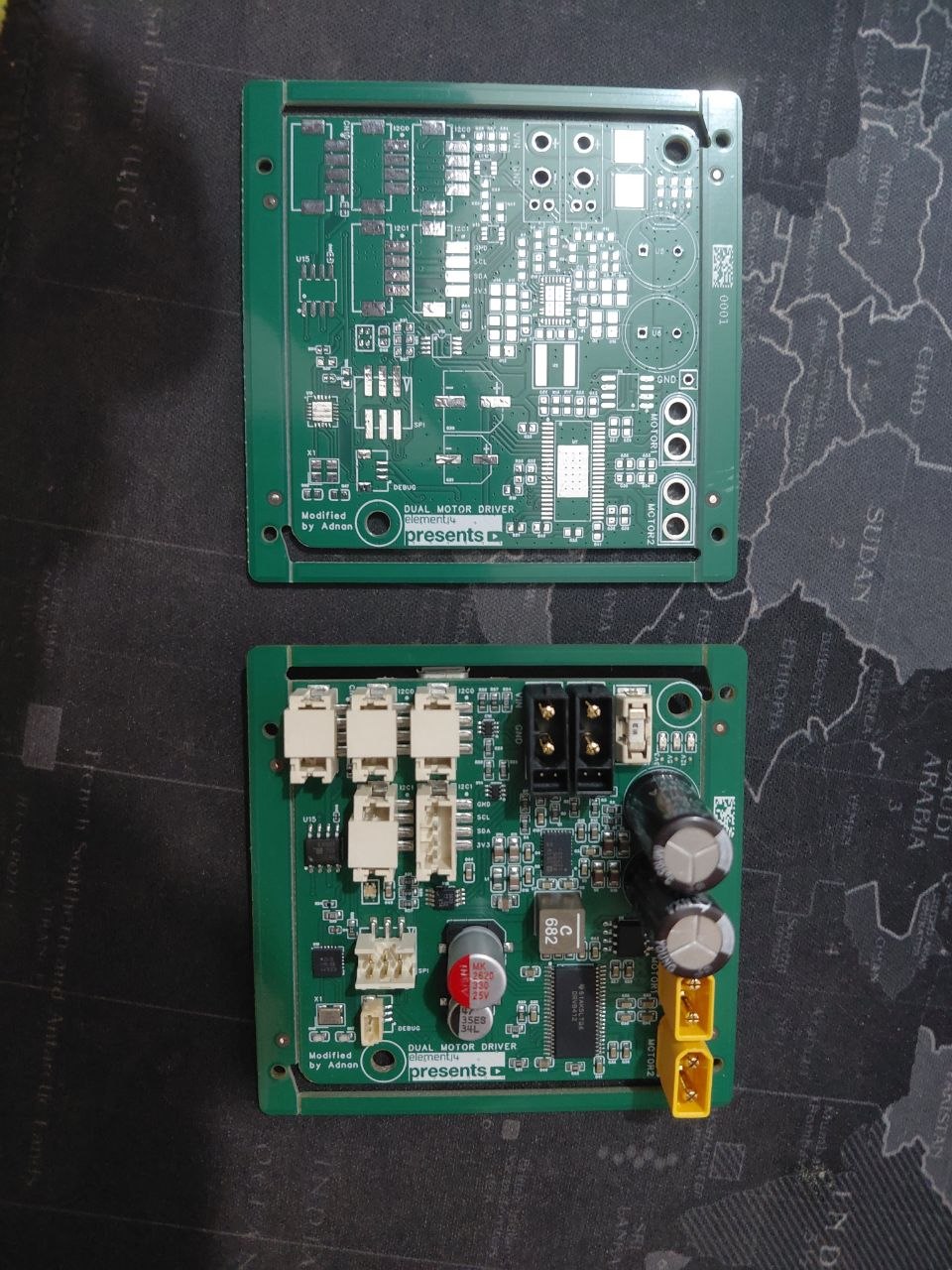
Custom CAN Motor Driver


- ✓ Custom CAN Motor Driver designed
- ✓ PCB completed in EasyEDA Pro
- ✓ BOM finalized
- ✓ CPL finalized
- ✓ Submitted for JLCPCB PCBA manufacturing
Production status
Manufacturing Partners
JLCPCB is handling PCB and PCBA manufacturing. JLC3DP is supporting mechanical part manufacturing for the rover structure.
Printed parts ~3kg filament

| Qty | Part | Notes |
|---|---|---|
| 88 | Clip2n125 | Print extra for spares |
| 12 | Clip3n20 | Print extra for spares |
| 6 | Wheel Hub | Modified for JGB37-520 D-shaft |
| 6 | JGB37-520 Motor Bracket | Redesigned mount |
| 6 | JGB37-520 Motor Coupler | Wheel-to-motor connection |
| 4 | LDX-227 Coupler | Redesigned for 25T spline |
| 4 | LDX-227 Bracket | Redesigned for servo dimensions |
| 6 | Wheel | |
| 4 | Steering Knuckle | Modified geometry |
| 4 | Body Corner | |
| 2 | DiffBrace / DiffLink | |
| 1 | DiffLower / DiffUpper | |
| 2 | Rod Support | |
| 1 | Power Panel | Updated for new electronics layout |
| 2 ea | Fixed/Front/Rear Knuckle, Bogie Wheels, Bogie Body, Rocker, Rocker Body Mount, DiffEnd, Battery Tray | Mirrored pairs |
Shafts Steel for diff, alu/steel for rest
| Qty | Length (mm) | Part |
|---|---|---|
| 1 | 300 | Differential Shaft |
| 6 | 50 | Wheel Axle Shaft |
| 4 | 61 | Steering Shaft |
| 2 | 66.5 | Suspension Bogie Pivot |
| 2 | 84 | Suspension Rocker Pivot |
Hardware
| Qty | Part | Notes |
|---|---|---|
| 4 | Hiwonder LDX-227 Servo | Steering |
| 6 | JGB37-520 12V 100RPM DC Gear Motor | Drive |
| 6 | Motor Shaft Couplers | JGB37-520 D-shaft compatible |
| 30 | 608 Bearings | |
| 300 | M3x8mm Socket Head Screws | |
| 28 | M3x16mm Socket Head Screws | |
| 300 | M3 Washers + Nuts | |
| 100 | M3 Threaded Inserts | |
| 100 | 5/16" E-Clips | |
| 22 | M3x8 Set Screws | |
| 2 | Turnbuckles | Steering linkage |
| 40 | 1/4" Brass Screws | |
| 1 | Motor Driver | 12V DC compatible |
| 1 | 12V Battery System |
Aluminum extrusion
| Qty | Length (mm) | Purpose |
|---|---|---|
| 4 | 385 | Main body, lengthwise |
| 4 | 245 | Main body, widthwise |
| 1 | 238 | Differential fixed beam |
| 2 | 182 | Rocker joint to front wheel |
| 2 | 161 | Rocker joint to bogie joint |
| 2 | 122 | Bogie joint to middle wheel |
| 2 | 117 | Bogie joint to rear wheel |
Updates
Fiscal sponsorship approved by Hack Club
Hack Club approved Team Bumblebee's fiscal sponsorship, enabling us to securely receive sponsor funding and manage payments for manufacturing, components, and other project expenses through Hack Club Bank.
Motor mounts done
All four mounts redesigned for JGB37-520. STEP files in repo.
Servo brackets updated
LDX-277 brackets done, 25T spline compatible.
EasyEDA partnership confirmed
EasyEDA Pro partnership secured for PCB design tooling and project support.
JLCPCB & JLC3DP partnership confirmed
Manufacturing partnerships secured with JLCPCB for PCB/PCBA fabrication and JLC3DP for structural printed parts.
PCB submitted for fabrication
Custom CAN motor driver PCB design files submitted to JLCPCB for fabrication.
PCBA submitted for assembly
BOM and CPL finalized and submitted to JLCPCB for full SMD assembly. Board production now underway.
PCB and PCBA completed
Motor driver PCB and full SMD assembly received. Electronics manufacturing is complete.
.jpg)